The Yamaha RX‑V673 owners manual offers a comprehensive guide to setup, operation, and troubleshooting․ It details connectivity options, audio‑video settings, and network features, ensuring users can fully exploit the receiver’s 4K pass‑through, Dolby Atmos, and AirPlay capabilities․ Enjoy audio now
Manual Overview and Key Features
The Yamaha RX‑V673 owners manual is a comprehensive 163‑page guide that covers every aspect of this mid‑range AV receiver․ It starts with a concise introduction that explains the unit’s purpose, key specifications, and safety guidelines․ The manual highlights the 7․2‑channel amplifier architecture, 4K Ultra‑HD pass‑through, and support for Dolby Atmos, DTS:X, and 3D audio formats․ A dedicated section details the integrated Wi‑Fi module, AirPlay 2, and DLNA functionality, enabling seamless streaming from smartphones, tablets, and networked media servers․ Built‑in HDMI‑CEC and HDMI‑ARC features allow one‑touch control of compatible devices and return‑audio transmission to soundbars or home‑theater systems․ The document also includes step‑by‑step instructions for initial setup, power‑on procedures, and firmware updates, along with diagrams of the front‑panel controls and rear‑panel input/output ports․ A quick‑start guide provides a rapid configuration path for users who prefer minimal setup, while a full configuration chapter walks through advanced settings such as speaker calibration, room correction, and network configuration․ The troubleshooting section lists common error messages, diagnostic codes, and recommended corrective actions, ensuring users can resolve issues without external support․ Warranty information, service center contact details, and a glossary of terms conclude the manual, providing a complete reference for owners to maximize performance while maintaining ease of use․ Additionally, the manual offers tips for maintaining the receiver’s longevity, such as proper ventilation, firmware backup procedures, and recommended cleaning practices․ It also covers the use of Yamaha’s proprietary audio processing algorithms, including the YPAO room calibration system, which automatically optimizes speaker levels and timing for the listening environment․ For users interested in expanding their home theater, the manual outlines compatible accessories, such as the RX‑V673‑S1 power conditioner and the RX‑V673‑B1 Bluetooth adapter, and explains how to integrate them seamlessly into the existing setup․

Setup and Installation

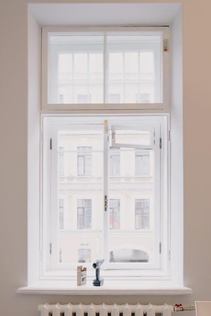
Begin by placing the RX‑V673 on a stable surface, ensuring adequate ventilation․ Connect the power cord, then link HDMI sources to the labeled inputs․ Use the included remote to navigate the menu, select “Setup Wizard,” and follow on‑screen prompts to configure audio, video, and network settings․ !
Connecting Audio and Video Sources
To connect your devices to the Yamaha RX‑V673, locate rear panel’s HDMI and component ports․ Insert an HDMI cable into “HDMI‑1” or “HDMI‑2” input for high‑definition content․ Use the 4‑channel optical or coaxial inputs for audio‑only streams If you have a Blu‑ray player, connect it via HDMI, select “HDMI‑1” as the source․ For older TVs, use the component or composite inputs․ After cables are seated, power on the receiver․ Follow the prompts to choose your region and set the TV resolution The manual recommends using a high cable (HDMI 2․0 or higher)․ For audio, connect the receiver’s speaker terminals to your wall‑mounted or bookshelf speakers․ Finally, test each input by selecting it from the “Input” menu If the image is distorted, check cable orientation and secure all connectors The RX‑V673 also supports Bluetooth audio pairing․ This allows wireless streaming of music or podcasts For networked devices, connect an Ethernet cable to the “LAN” port․ Refer to the manual wiring diagram for impedance, phase alignment, and power‑supply recommendations․ The PDF version includes a step‑by‑step guide to ensure proper cable routing and avoid signal loss․ If you encounter any difficulties, consult the troubleshooting section or contact Yamaha support for assistance․ Remember to keep the receiver’s firmware up to date to benefit from the latest performance improvements and bug fixes By following these guidelines, you’ll enjoy a seamless setup and optimal audio‑video experience with the Yamaha RX‑V673!

Audio Configuration
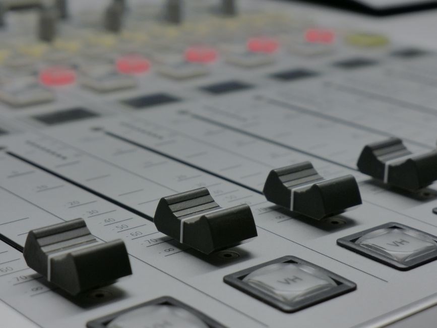
The Yamaha RX‑V673 manual details speaker wiring, impedance matching, and sound‑mode selection․ Use the “Speaker Setup” menu to assign front, center, surround, and sub‑woofer channels․ Enable Dolby Atmos or DTS:X for immersive 3‑D audio․ Adjust volume, balance, and equalizer for optimal sound․!!!!!!
Speaker Setup and Sound Modes

According to the Yamaha RX‑V673 owners manual, the first step in speaker configuration is selecting the appropriate speaker layout from the “Speaker Setup” menu․ The receiver supports 2‑, 3‑, 5‑, 7‑, and 9‑channel systems, allowing users to set up a standard 5․1, 7․1, or 9․1 surround sound system․ Each speaker—front left, front right, center, surround left, surround right, rear left, rear right, sub‑woofer, and optional height speakers—is individually labeled in the menu, and the manual instructs users to connect each speaker to its corresponding terminal, ensuring correct polarity and impedance (typically 8 Ω)․ After wiring, the receiver automatically performs a calibration test, prompting the user to place a test tone in the listening position․ The calibration adjusts speaker levels, distances, and crossover frequencies to achieve balanced sound throughout the room․ For advanced users, the “Manual Calibration” option allows fine‑tuning of each channel’s level, phase, and equalization․ The receiver also features a “Sound Mode” selector, offering presets such as Standard, Dynamic, Movie, Music, and Custom․ Standard mode provides a neutral sound signature, while Dynamic enhances bass and treble for a punchier experience․ Music mode prioritizes fidelity, reducing compression and preserving the original recording’s nuance․ The manual explains how to access the “Sound Mode” menu, select a preset, and tweak parameters using the remote control or on‑screen interface․ By following the step‑by‑step instructions, users can configure their speaker system for optimal performance, ensuring clear dialogue, immersive surround, and accurate imaging in any environment․ Settings saved

Video Configuration
The Yamaha RX‑V673 manual explains HDMI settings, 4K pass‑through, HDR support, and audio‑return channel configuration․ Adjust resolution, enable 4K upscaling, set HDMI‑CEC, and choose video mode for optimal picture quality․ Supports HDR10 and Dolby Vision․ for clear
HDMI Settings and 4K Pass-Through
In the Yamaha RX‑V673 owners manual, the HDMI configuration section details how to enable and optimize 4K pass‑through for the best visual experience․ The receiver supports 4K/60Hz input and output, allowing you to connect a 4K Blu‑ray player, gaming console, or streaming box and have the signal delivered unaltered to a 4K TV․ To activate 4K pass‑through, navigate to the HDMI Settings menu, select the desired HDMI port, and enable the 4K Pass‑Through toggle․ The manual also explains how to adjust the HDMI‑CEC function for automatic power control and input switching, and how to set the HDMI‑Audio Return Channel (ARC) for audio playback from the TV․ For HDR content, the RX‑V673 automatically detects HDR10 and Dolby Vision signals and passes them through without downscaling, provided the TV supports the format․ If your TV lacks HDR support, the receiver can downscale the image to SDR while preserving the original 4K resolution․ The manual recommends using the HDMI‑Link feature to connect multiple HDMI sources via a single port, reducing cable clutter․ HDMI‑Audio Format setting lets you select Dolby Digital DTS or PCM output․ Finally, the manual advises checking the firmware version and updating it if necessary, as newer firmware may improve 4K handling and support HDR! By following these steps, users can fully leverage the RX‑V673’s 4K pass‑through capabilities for a seamless home‑theater experience․!

Network and Streaming Features
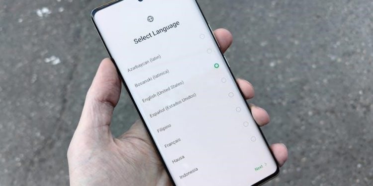
The RX‑V673 connects via Wi‑Fi or Ethernet, enabling AirPlay, DLNA, Chromecast․ Use the Network menu to set Wi‑Fi credentials, assign IP, or enable UPnP․ The receiver supports Spotify, Pandora, YouTube Music through Yamaha MusicCast, allowing playback now․
Enjoy high‑quality streaming on device․
Wi‑Fi, AirPlay, and DLNA Setup
Connecting the RX‑V673 to your home network is straightforward․ First, navigate to the Network menu via the remote or on‑screen interface․ Select “Wi‑Fi Setup” and choose your SSID from the displayed list․ Enter the password using the on‑screen keyboard; the receiver confirms a successful connection with a green checkmark․ If you prefer a wired connection, plug an Ethernet cable into the back of the unit and the router; the device will automatically detect the link and obtain an IP address via DHCP․ For advanced users, the Network menu also offers static IP configuration, DNS server selection, and port forwarding options for streaming services․ Once the network is established, enable AirPlay by selecting “AirPlay” in the Network submenu․ The receiver will broadcast its AirPlay name, allowing iOS and macOS devices to stream audio or video directly to the RX‑V673․ To use DLNA, enable “DLNA/UPnP” in the same submenu; the unit will then appear as a media server on compatible smart TVs, smartphones, and tablets․ Streaming apps such as Spotify, Pandora, and YouTube Music can be accessed through Yamaha’s MusicCast interface, which syncs multiple receivers for a multi‑room experience․ Finally, confirm that the firmware is up to date by selecting “System Update” in the Network menu; this ensures optimal performance and compatibility with the latest streaming protocols․ Enjoy seamless, high‑quality audio and video across all your devices․․․․․․․․․․․․․․․․․
Remote Control and User Interface
The RX‑V673 remote offers navigation with buttons for source, volume, and menu․ The on‑screen interface displays source icons, equalizer presets․ Touch‑pad input allows channel changes, and the “Smart” button launches MusicCast for multi‑room streaming ․
Using the Remote and On‑Screen Menu

Using the remote control and on‑screen menu of the Yamaha RX‑V673 is straightforward yet powerful․ The remote’s main buttons—Power, Volume, Mute, and Source—allow you to quickly toggle the receiver’s state, adjust levels, and switch between HDMI, optical, and Bluetooth inputs․ The “Menu” button opens a full‑screen menu on the TV or monitor, where you can navigate with the arrow keys or the touchpad․ The menu is divided into major sections: System, Audio, Video, Network, and Settings․ Within each section, sub‑menus let you tweak speaker calibration, sound modes, picture settings, Wi‑Fi configuration, and firmware updates․ The “Quick Menu” (accessed by pressing the “Quick” button) offers a condensed view of the most frequently used options, such as source selection, volume, and mute․ For advanced users, the “Setup” menu includes a “Speaker Setup” wizard that measures room acoustics and automatically configures speaker levels, distances, and delays․ The “Audio” tab provides options for Dolby Atmos, DTS‑X, and YPAO (Yamaha Parametric Acoustic Optimizer)․ The “Video” tab allows you to enable 4K pass‑through, adjust HDR formats, and set HDMI‑CEC․ The “Network” tab covers Wi‑Fi, AirPlay, and DLNA settings, while “Settings” includes power‑on behavior, sleep timers, and remote control pairing․ The on‑screen menu also supports a “Help” function that displays context‑sensitive information for each menu item․ Users can save custom presets for different rooms or viewing scenarios, and the remote’s “Preset” buttons can instantly recall these settings․ Finally, the receiver’s firmware can be updated via the “System” menu, ensuring the latest features and bug fixes are available․
Additionally, the receiver’s on‑screen menu supports a “Preset” function where you can name and store up to 10 custom configurations․ The remote’s “Preset” buttons (1–10) instantly switch between these configurations, making it easy to switch from a movie‑mode preset to a music‑mode preset․ The “Audio” tab also offers a “Virtual Surround” option that simulates a 7․2‑channel surround sound experience even with fewer speakers․ For users who prefer manual control, the “Equalizer” sub‑menu allows you to adjust bass, mid, and treble levels in 1‑dB increments․ The “Video” tab’s “HDMI‑CEC” setting can be enabled to allow the receiver to control connected devices automatically․ Finally, the “System” tab’s “Firmware Update” option checks for the latest software and guides you through the update process, ensuring your receiver stays current with new features and security patches․

Troubleshooting and Support
Refer to the RX‑V673 manual for error codes, reset procedures, and firmware updates․ Contact Yamaha support via phone, email, or the official website․ Warranty covers manufacturing defects; service centers handle repairs and parts replacement․ Check firmware!!!
Common Issues, Warranty, and Service Information
Users often report a few recurring problems with the RX‑V673․ The most frequent is a “no audio” or “no video” output after a firmware update; this is usually resolved by resetting the receiver to factory defaults or by re‑installing the latest firmware via the USB or network update option․ HDMI handshake errors can occur when the source device is not 4K‑capable; disabling 4K passthrough or updating the source firmware usually fixes the issue․ Wireless connectivity problems, such as Wi‑Fi dropouts or AirPlay lag, are commonly caused by interference or an outdated firmware; a quick reboot or a firmware upgrade often restores stable performance․ If the receiver displays a “system error” code, consult the error‑code list in the manual and follow the recommended troubleshooting steps․ The RX‑V673 is covered by Yamaha’s standard one‑year limited warranty, which protects against manufacturing defects and covers parts and labor at authorized service centers․ For extended coverage, Yamaha offers a paid extended warranty program that can be purchased during the initial purchase or within 30 days thereafter․ Service requests can be submitted online via Yamaha’s support portal, by phone, or by visiting an authorized Yamaha dealer․ Before sending the unit, it is advisable to back up any custom settings and to note the serial number, which can be found on the rear panel or in the system information menu․ The manual provides detailed instructions for preparing the unit for shipping, including how to safely remove the power cord and label the package․ For quick assistance, the online FAQ and community forums are excellent resources, and the manual’s troubleshooting section lists step‑by‑step solutions for common issues․ By following the guidelines in the owners manual, most problems can be resolved at home, and warranty claims can be processed efficiently by Yamaha’s support network․ For additional help, consult Yamaha’s online support center, which offers chat, FAQs, and firmware updates!